Executive Summary
This paper provides an analysis of two software failures. Ariane 5 and London Ambulance Service Computer Aided Despatch system.
A root cause analysis of each failure is followed by a causal loop analysis. The causal loop analysis has been developed as an organisational model suitable for use in assessing the capability of organisations to undertake complex project and systems engineering activities. Organisational interfaces are depicted as risks across organisational boundaries or interfaces. The importance of risk management in managing the potential negative impact of unexpected emergent system properties is described.
Recommendations are provided to avoid similar failures in the future. The recommendations combined with the Causal Loop Model provide a tool for assessing organisational capability for managing complex systems.
Background
Both the Ariane 5 and London Ambulance Service (LAS) Computer Aided Despatch (CAD) system failures are well publicised examples of software failures.
Ariane 5
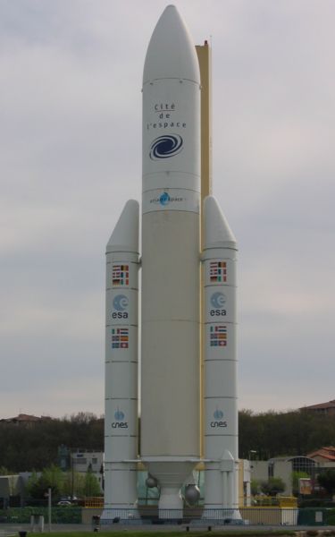
Ariane 5 is a European expendable launch system designed to deliver geostationary or low earth payloads. It is manufactured by a consortium of the European Space Agency (ESA), the Centre National d'Etudes Spatiales (CNES), and EADS Astrium Space.
It succeeded the Ariane 4 and reused a number of systems including software modules. Development took 10 years and cost €7 billion. ESA originally designed Ariane 5 to launch the manned mini shuttle Hermes, and thus intended it to be "human rated" from the beginning. After ESA cancelled Hermes, the rocket became a purely robotic launcher.1
The Ariane 5 initial test flight (Ariane 5 Flight 501) on 4 June 1996 failed, with the rocket self-destructing 37 seconds after launch because of a malfunction in the control software, which was arguably one of the most expensive computer bugs in history. A data conversion from 64-bit floating point to 16-bit signed integer value had caused a processor trap (operand error). The floating point number had a value too large to be represented by a 16-bit signed integer. The requirement to contain processor duty cycle to below 80% led to the inclusion of exception handling for some but not all of the floating point variables.
The Ariane 5 launch trajectory differed from Ariane 4 with an increased horizontal bias (or lateral velocity) that was never modelled or simulated prior to launch. The Inertial Reference System (SRI) processor specification called for the processor hardware to be shutdown if a software exception was experienced. This specification was not failsafe and led to the shutdown of the primary and backup processors that were fully functioning before, during and after the software exception occurred.
The requirement to continue calculating the horizontal bias after launch was a legacy requirement for Ariane 4 to enable a rapid relaunch countdown if required. This feature was used once in 1989 but was not relevant to Ariane 5 as the launch sequence differed substantially.2 The failure occurred because an unnecessary calculation led to system shutdown.
London Ambulance Service (LAS) Computer Aided Despatch (CAD) System
The London Ambulance Service, at the time of this failure was the largest ambulance service in the world serving nearly 7 million people over a 600 mi^2^ area in the city of London. In 1987 the LAS tendered for a Computer Aided Despatch system to replace the existing manual despatch system as described by Kwiatkowski (2005)3
"The LAS despatch system is responsible for: receiving calls; despatching ambulances based on an understanding of the nature of the calls and the availability of resources; and, monitoring progress of the response to the call. A computer-aided despatching system was to be developed and would include an automatic vehicle locating system (AVLS) and mobile data terminals (MDTs) to support automatic communication with ambulances. This system was to supplant the existing manual system.
The existing system dealt with:
- 5000 patients per day
- 2000-2500 calls per day
- 1000-1200 999 calls per day
The new CAD system was expected to meet a new standard that required a 3 min mobilization.4
The events that lead to failure of the LAS CAD system are as follows:
- Lead Up: The First Try5 a. Development began in 1987 b. Specification changed drastically in 1989 c. Cancelled October 1990 after two failed tests
- Lead Up: Specification and Bidding a. Extremely ambitious design b. Lead Up: System Development c. Underestimated complexity of software (4% of budget) d. No test plan
- Lead Up: Warning Signs a. First two phases plagued by problems b. major system crash c. Computer and safety experts warned government of serious flaws d. Dismissed by Health Secretary
- Failure: Day 1 & 2 a. 2 serious errors, 44 operational errors and 35 minor problems known
- Failure: Day 3 a. October 27 1992 system returned to Phase 2 b. Up to 46 people may have died prematurely
- Failure: Day 10 a. Back up systems failed to function adequately
Preliminary Failure Analysis
According to Ramberger and Laprie (2004)6 there are 3 classes of software impairment. Namely:
- Faults = detected or assumed reason of an error
- Errors = portion of a system state which necessarily leads to a subsequent failure: The error is an indicator for a failure that occurs or has occurred.
- Failures = a deviation between the delivered system function and the required one
Both the Ariane 5 and London Ambulance Service systems failed. Ariane 5 spectacularly with the complete destruction of the launch vehicle and payload and the London Ambulance Service Computer Aided Despatch system which was never accepted into service due to the complete failure of the system.
Preliminary Capability Assessment
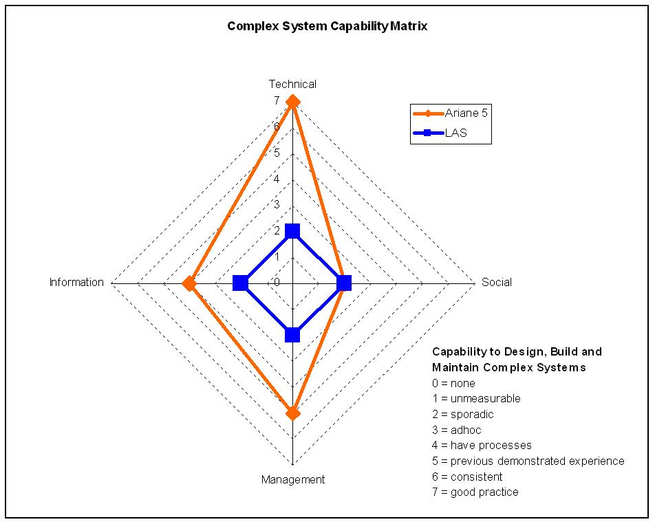
A literature search 7 8 9 10 11 12 was undertaken on the publicly available information relating to both the Ariane 5 and LAS CAD system failures. The investigation of the failures focussed on the professionalism and behaviour of both projects as the technical reason for failure, particularly in the case of Ariane 5 is well known. Initially both failures appeared to show little similarity between the factors that led to failure. Clearly a more rigorous system analysis was required. System in this context includes technical, social, management and information. During the early stage of the investigation it was helpful to compare the capability of both the Ariane 5 and LAS CAD teams prior to the root cause analysis of the organisational failures. Figure 1 - Capability Matrix is the authors high level assessment criteria to rate the ability of each team to deal with a complex system over the lifecycle. In this case during the design and acquisition phase.
Most of the literature available provided the conclusions but not the means by which the conclusions were derived. Particularly in the case of the LAS CAD system project which was clearly out of control from day one. The Ariane 5 project was clearly a more professional organisation which had developed successful launch platforms in the past. This is indicated in Figure 1 - Capability Matrix.
Detailed Failure Analysis
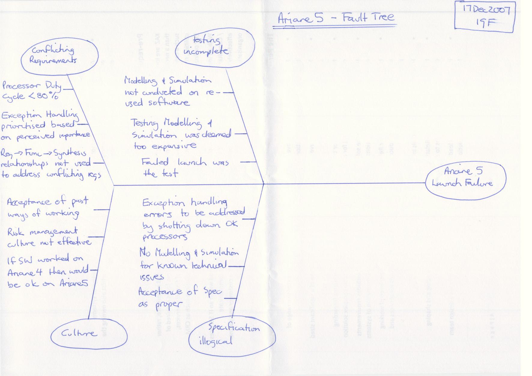
A root cause analysis using a fault tree or Ishikawa diagrams was then undertaken to capture those factors which either directly led to or were clearly contributing factors to the failures. This approach indicated some similarities and differences between the two failures as indicated in Figure 2 - Ariane 5 Fault Tree and
Figure 3 - London Ambulance Service Fault Tree.
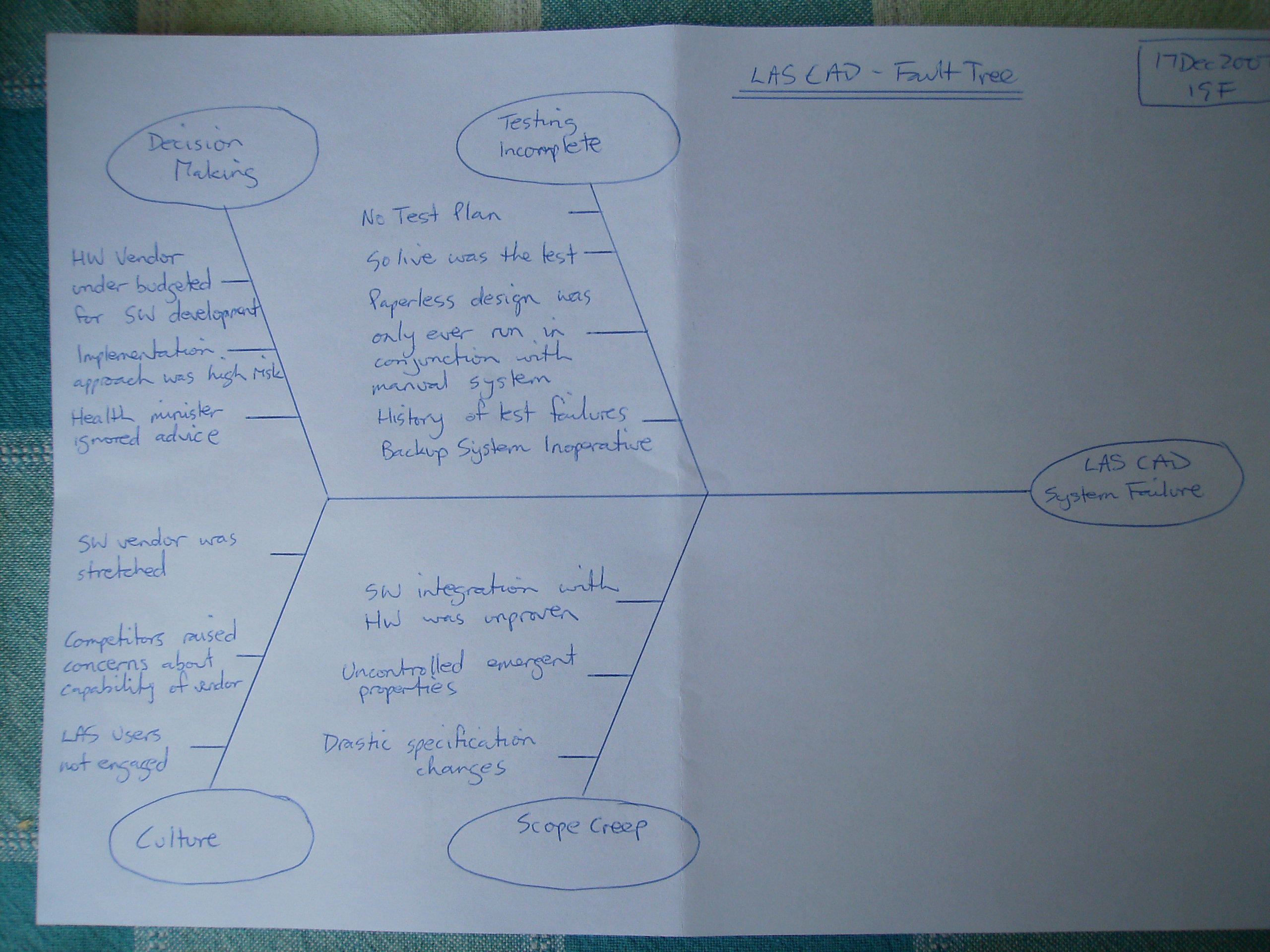
[]{#__RefHeading___Toc185753302 .anchor}Figure 3 - London Ambulance Service Fault Tree
Causal Loop
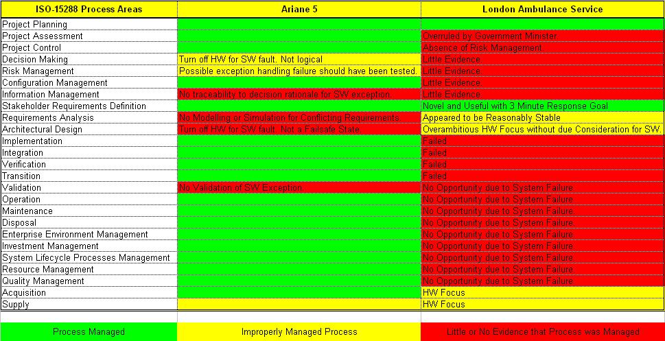
Both the preliminary capability assessment in Figure 1 - Capability Matrix and the detailed capability assessment in Figure 11 - ISO-15288 Process Evaluation Mapping describe the organisational factors that led to failure. In order to better understand the failures and in order to provide meaningful recommendations a model of each organisation is required to enable evaluation of ‘what if’ scenarios.
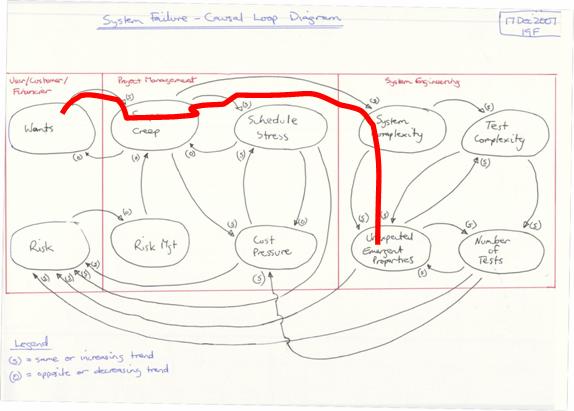
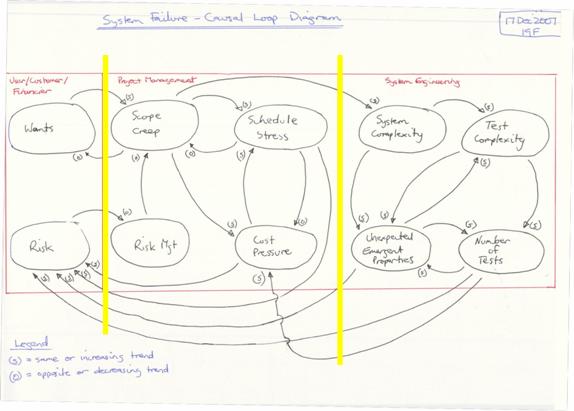
A Causal Loop Diagram was developed as a model of the organisations. To allow comparisons the Causal Loop Diagram was refined to represent both the Ariane 5 and the LAS CAD organisations. After a number of iterations of the model it became evident that the model represented both the stakeholders (users, customers, financiers) and the organisations responsible for developing the systems. The system developing organisation was divided in two organisational streams. Namely project management and systems engineering. The model is delineated into the 3 groupings as shown in Figure 4 - Failure Modes and Relationships Causal Loop.
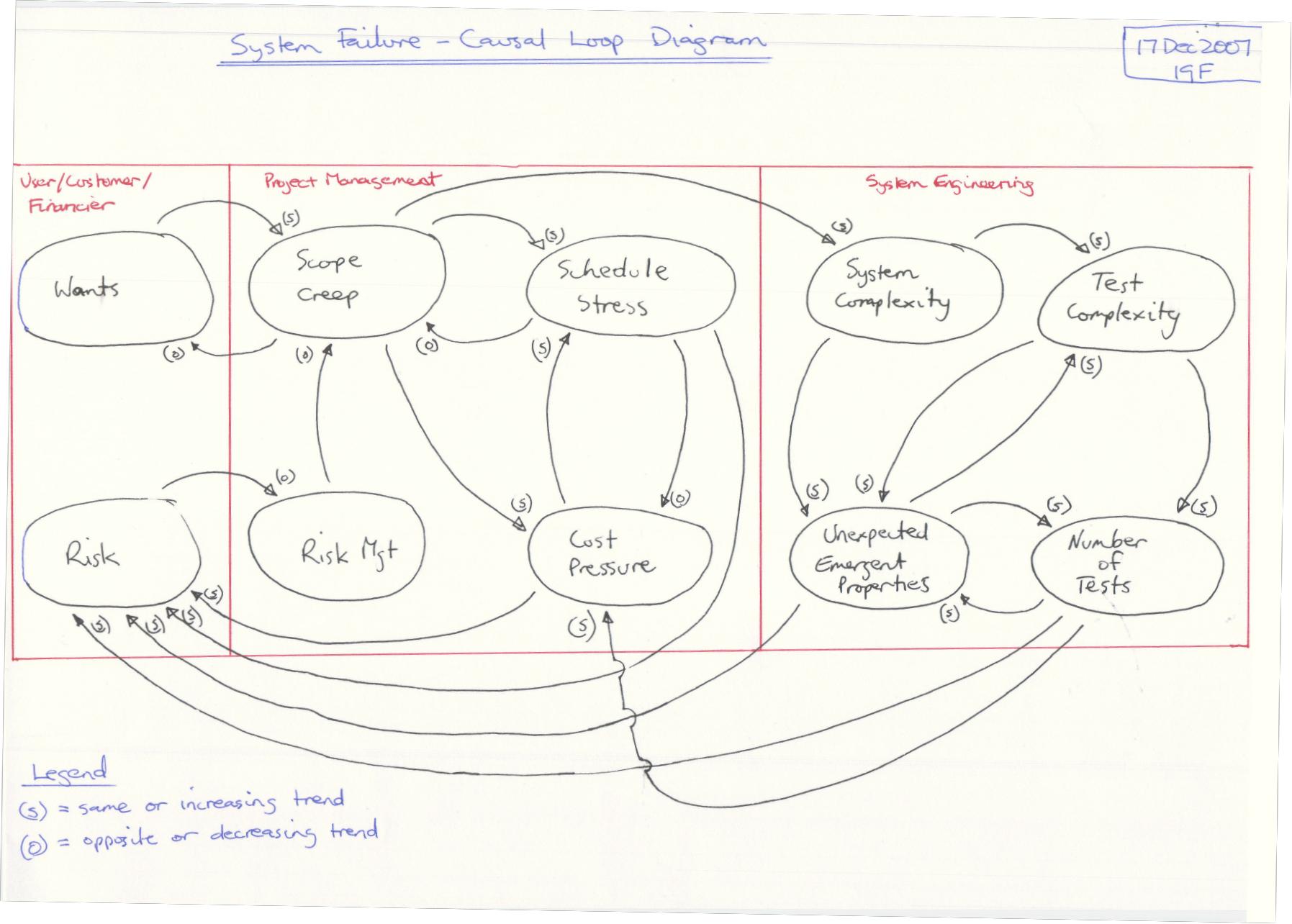
The causal loop diagram depicts the following:
- balancing loops (closed loop control)
- unbalanced loops (closed loop uncontrolled) and
- open loops (open loop uncontrolled)
These loops relate to the organisation. The purely technical aspects of the system are represented within the “System Complexity” space in Figure 4 - Failure Modes and Relationships Causal Loop. No further technical detail is provided as the focus in this paper on organisational issues.
Note:
- User, Customer, Financier also includes the public, government, etc
- Project Management also includes HR, Finance, Admin, Commercial, Marketing, Legal functions etc.
- Systems Engineering also includes all engineering disciplines and in cases of manufacturing and support all those technical functions
- For this analysis only the design and acquisitions phase of the systems engineering lifecycle is considered.
Balanced Loops
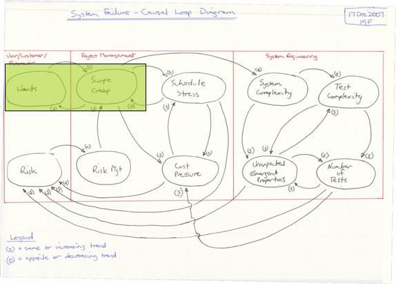
In Figure 5 - LAS CAD Balanced Loop 1 we can see that user, customer, financier wants are met by allowing scope creep. This is a common trend in poorly managed projects. LAS CAD suffered this problem but Ariane 5 was better managed.
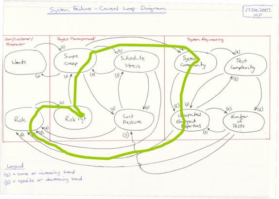
In Figure 6 - LAS CAD Balanced Loop 2 we can see that Risk Management is key to managing the impact of scope creep. Numerous other paths can be traced through the Project Management and Systems Engineering segments but all require Risk Management to remain balanced and in control.
Unbalanced Loops
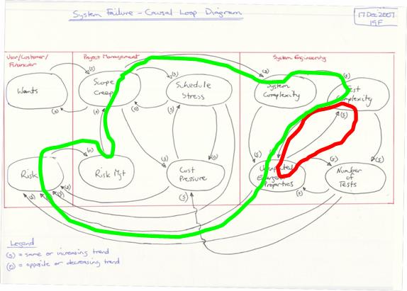
In Figure 7 – Ariane 5 Balanced –vs- Un Balanced Loop we can see that increasing test complexity leads to a probable increase in unexpected emergent properties. (red loop) The assumption by the Ariane 5 project team that as they were " … reusing Ariane 4 software then they wouldn’t need to test it" assumption is risky. If the reuse assumption had been followed through to Risk Management then this unbalanced decision making could be managed through a balancing loop. (green loop)
Open Loops
If we consider the LAS CAD project as an open loop we see the result being unexpected emergent properties that are effectively unmanaged. Constant surprises leading to either confusion or unplanned work result from this behaviour. The only way to close and balance this loop is by Risk Management. Refer to Figure 7 – Ariane 5 Balanced –vs- Un Balanced Loop for an example.
Integration Issues
The Causal Loop diagram also defines the interfaces across the boundaries of the user, customer, financier, project management and systems engineering. In Figure 9 - Causal Loop Organisational Interfaces we can see that the interfaces across and through the organisation primarily relate to risk. The only controlling interface is from Risk to Risk Management. All other interfaces are increasing or uncontrolled interfaces. From this simple organisational interface diagram we can see that if risk is not controlled then we will potentially and probalistically be subject to an uncontrolled outcome. (This is equivalent to gambling) In the case of Ariane 5 and LAS CAD this uncontrolled outcome led to catastrophic failure and in the case of LAS CAD loss of human life.13
From Figure 9 - Causal Loop Organisational Interfaces we can see that the following contributors impact our management of risk:
-
Project Management
a. Schedule Stress
b. Cost Pressure
-
Systems Engineering
a. Unexpected Emergent Properties
b. Number (and complexity) of Tests
The contribution of both Project Management and Systems Engineering both create risk that needs to be managed. We can not simply “blame” Project Management or Systems Engineering and we certainly can’t justify “blaming” the customer with this model.
Conclusions and Recommendations
Conclusions
The analysis started with a literature review and subjective assessment of each organisation’s capability to deal with complex systems. Next a root cause analysis of the contributing factors leading to failure is depicted in an Ishikawa diagram. Finally a causal loop diagram was constructed to show how the failures occurred. The causal loop diagram allows ‘what if’ scenarios to be considered to support the recommendations.
The failure analysis steps were as follows:
- MIST (authors proprietary capability assesment matrix)
- Fault Tree
- Causal Loop
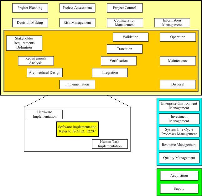
In order to benchmark the findings it is necessary to baseline or compare the findings with a know standard or framework. This allows comparison of other failures with the findings in this paper and minimises author bias. ISO-15288, System Life Cycle Processes14, was selected as the most appropriate standard / framework. Appendix Figure 13 - ISO-15288 Process Areas depicts ISO-15288 in the context of the system engineering V Diagram. It is now clear how different both organisations are. Compare Figure 1 - Capability Matrix with Figure 11 - ISO-15288 Process Evaluation Mapping. Ariane 5 was clearly a more professional organisation than LAS CAD. However both suffered catastrophic failures.
ISO-15288 Detailed Capability Assessment
Recommendations
As indicated, in Figure 1 - Capability Matrix and Figure 11 - ISO-15288 Process Evaluation Mapping, being technically competent is not sufficient to avoid failure. The Ariane 5 organisation was clearly more technically competent than the LAS CAD project. In essence we can consider the 4 capabilities necessary for an organisation to have the capability to deal with complex systems as depicted in Figure 12 - Capability Matrix (Figure 1).
Technical competence needs no explanation and is demonstrable by objective means. But social, information and management competencies are often more esoteric and good practice is not the norm in either society or organisations. Consider the non technical competencies in more detail.

Social
A cohesive team is necessary for success in any group venture. This rule applies to our cave dwelling ancestors hunting for survival many tens of thousands of years ago. Commonly the importance of good social networking is ignored by many organisations. The authors own experience in the workforce of over 25 years has only provided 3 or 4, out of 43, good social network experiences in the workplace.
Recommendation 1
The workplace atmosphere should replicate a cohesive family type unit with common goals
Recommendation 2
Office layouts should be arranged around the goals and not functions or ‘silos’
Information
Management of information, separate to any formal configuration management which is more technical, should include tacit and documented information management with the goal of full traceability. Local computer storage and uncontrolled document growth are both inhibitors to information management.
Even a professional organisation such as that responsible for the Ariane 5 could not provide traceability of decisions that led to failure.
Recommendation 3
The paperless office is the goal. The authors experience has provided 2 examples, from 43 workplace experiences, of the benefits of the paperless office. The key metric here is time lost searching for information and then confusion when multiple copies are found. In the paper based office this metric is upwards of 20% of a person’s time or more. Unfortunately unless a functioning paperless office has been experienced typical ‘cut and paste’ cultures dominate through all levels of management and most functions.
Recommendation 4
Centrally managed relational database storage of information should be preferred over uncontrolled unrelated document storage. Data queries are never fully understood in advance. An ability to query the organisational dataset(s) is required.
Management
In the authors experience management is probably the least professional endeavour in the workplace. Formal qualifications in management are rare. Good management of complex systems is all about risk management. Risk to schedule, cost, performance, quality and in some cases human life. Both Ariane 5 and LAS CAD failed to demonstrate robust risk management behaviour. Robust Risk Management requires access to all information, formal, informal and tacit in order to make decisions which appropriately manage risk. More than any other factor risk management would have contained the potential for failure of both the Ariane 5 and LAS CAD projects.
Recommendation 5
All decisions should be assessed in the context of risk (and opportunity). The primary portal for traceability to all decisions should be via a risk management framework. A risk register in a spreadsheet is not risk management it is a document approach to a complex relational information management requirement. (see recommendation 4)
Appendix
ISO-15288 – System Engineering / Integration Framework
Bibliography
Continue reading articles in my Systems Engineering series
Series: [Systems Engineering]
-
ARIANE 5, Flight 501 Failure, Report by the Inquiry Board, The Chairman of the Board :Prof. J. L. LIONS ↩︎
-
Lec01hand.pdf 06-15256 Safety Critical Systems and Software Reliability Prof. Marta Kwiatkowska School of Computer Science University of Birmingham www.cs.bham.ac.uk Level 4 Module 2005/06 ↩︎
-
London Ambulance Service Computer Aided Disaster March 21, 2003 Sam Hyland hylandsb@mcmaster.ca Software Engineering 3B03 ↩︎
-
London Ambulance Service Computer Aided Disaster March 21, 2003 Sam Hyland hylandsb@mcmaster.ca Software Engineering 3B03 ↩︎
-
Experience Report: Error Distribution in Safety-Critical Software & Software Risk Analysis Based on Unit Tests, Stephan Ramberger (stephan.ramberger@arcs.ac.at) Thomas Gruber (thomas.gruber@arcs.ac.at) ARC Seibersdorf research GmbH, Siebersdorf Research, 20 Sep 2004 ↩︎
-
Lec01hand.pdf 06-15256 Safety Critical Systems and Software Reliability Prof. Marta Kwiatkowska School of Computer Science University of Birmingham www.cs.bham.ac.uk Level 4 Module 2005/06 ↩︎
-
London Ambulance Service Computer Aided Disaster March 21, 2003 Sam Hyland hylandsb@mcmaster.ca Software Engineering 3B03 ↩︎
-
A Comedy of Errors: the London Ambulance Service case study Anthony Finkelstein & John Dowell School of Informatics, City University, UK {acwf@soi.city.ac.uk, johnd@soi.city.ac.uk} ↩︎
-
A Case Study in the Integration of Accident Reports and Constructive Design Documents Chris Johnson Department of Computing Science, University of Glasgow, Glasgow, G12 8QQ, UK. cited as D. McKenzie, Computer-Related Accidental Death: An Empirical Exploration, Science and Public Policy, (21)4:233-248, 1994 ↩︎
-
Ariane 5: Who Dunnit? soapbox basharnuseibeh imperial college, London ↩︎
-
Experience Report: Error Distribution in Safety-Critical Software & Software Risk Analysis Based on Unit Tests, Stephan Ramberger (stephan.ramberger@arcs.ac.at) Thomas Gruber (thomas.gruber@arcs.ac.at) ARC Seibersdorf research GmbH ↩︎
-
Lec01hand.pdf 06-15256 Safety Critical Systems and Software Reliability Prof. Marta Kwiatkowska School of Computer Science University of Birmingham www.cs.bham.ac.uk Level 4 Module 2005/06 ↩︎
-
ISO/IEC 15288, System Life Cycle Processes, http://www.15288.com/ ↩︎